Sollte es während der Fahrt zu regnen beginnen, wird das Schiebedach automatisch geschlossen.
Voraussetzung: RLS und SHD
Preis: 10,00 € inkl. MwSt
Sollte es während der Fahrt zu regnen beginnen, wird das Schiebedach automatisch geschlossen.
Voraussetzung: RLS und SHD
Preis: 10,00 € inkl. MwSt
Verfasser: Markus Plamberger
Letzte Änderung: 2020-06-28 13:34
Sobald der Automatikmodus der Lüftung gewählt wird, schaltet der Klimakompressor standardmäßig mit dazu.
Dies ist besonders im Winter oder an kühleren Tagen unnötig und verbraucht zusätzlichen Treibstoff.
Dieses Verhalten kann durch eine Programierung verändert werden.
Preis: 19,00 € inkl. MwSt
Verfasser: Markus Plamberger
Letzte Änderung: 2020-06-28 13:37
Sobald der Automatikbetrieb der Klimaanlage gewählt wird, ist die stärke des Lüfters nicht mehr über dei LEDs sichtbar.
Dies kann geändert werden, dass die Gebläsestufe trotz Automatikbetrieb angezeigt wird.
Preis: 19,00 € inkl. MwSt
Verfasser: Markus Plamberger
Letzte Änderung: 2020-06-28 13:39
BMW Entwicklungscodes
501 - (1952–1958) Sechszylinder-Limousine
502 - (1954–1964) Achtzylinder-Limousine
503 - (1956–1959) Coupé und Cabrio mit Achtzylinder
505 - (1955) Pullman-Limousine mit Achtzylinder(Prototyp)
507 - (1955–1959) Achtzylinder-Roadster
532 - (1962–1965) BMW 3200 CS Achtzylinder-Coupé; ein Cabrio als Einzelstück
100 - (1955–1962) BMW Isetta
101 - (1955–1962) BMW Isetta 250
102 - (1956–1962) BMW Isetta 300
103 - (1955–1962) BMW Isetta
106 - (1957–1959) BMW 600
107 - (1959–1965) BMW 700
110 - (1961–1964) BMW 700 Cabriolet
114 - (1966–1977) BMW 02 (1502, 1600-2, 1602–2002ti)
115 - (1963–1964) Neue Klasse BMW 1500
116 - (1964–1966) Neue Klasse BMW 1600
118 - (1963–1971) Neue Klasse BMW 1800-1800TI/SA
120 - (1966–1970) Neue Klasse Coupé BMW 2000C/CS
121 - (1966–1972) Neue Klasse BMW 2000–2000tii
E3 - (1968–1977) 2500–3,3 l
E6 - (1971–1975) BMW 02 als Touring
E7 - (1972) BMW 02 Elektroversion zu den Olympischen Spielen 1972
E9 - (1968–1976) 2800CS–3,3CSI
E10 - (1971–1975) BMW 02 (2002, 2002tii)
E12 - (1972–1981) BMW 5er-Reihe
E20 - (1968–1975) BMW 02 (2002 turbo)
E21 - (1975–1983) BMW 3er-Reihe
E22 - (1969) Neue Klasse Mittelmotor-Prototyp
E23 - (1977–1986) BMW 7er-Reihe
E24 - (1976–1989) BMW 6er-Reihe
E25 - (1972) BMW Turbo X1 (Prototyp)
E26 - (1978–1981) BMW M1
E28 - (1981–1987) BMW 5er-Reihe
E30 - (1982–1994) BMW 3er-Reihe
E31 - (1989–1999) BMW 8er-Reihe
E32 - (1986–1994) BMW 7er-Reihe
E34 - (1987–1995) BMW 5er-Reihe
E36 - (1990–2000) BMW 3er-Reihe
E36/7 - (1995–2002) BMW Z3 Roadster
E36/8 - (1998–2002) BMW Z3 Coupé
E38 - (1994–2001) BMW 7er-Reihe
E39 - (1995–2004) BMW 5er-Reihe
E46 - (1998–2007) BMW 3er-Reihe
E52 - (2000–2003) BMW Z8
E53 - (1999–2006) BMW X5
E60 - (2003–2010) BMW 5er Limousine
E61 - (2004–2010) BMW 5er Touring
E63 - (2003–2011) BMW 6er Coupé
E64 - (2004–2010) BMW 6er Cabrio
E65 - (2001–2008) BMW 7er-Reihe
E66 - (2002–2008) BMW 7er-Reihe als Lang-Version
E67 - (2002–2008) BMW 7er-Reihe als Security-Version
E68 - (2006–2007) BMW Hydrogen 7
E70 - (seit 2006) BMW X5
E71 - (seit 2008) BMW X6
E72 - (2009–2011) BMW ActiveHybrid X6
E81 - (2007–2012) BMW 1er Dreitürer
E82 - (seit 2007) BMW 1er Coupé
E83 - (2003–2010) BMW X3
E84 - (seit 2009) BMW X1
E85 - (2002–2008) BMW Z4 Roadster
E86 - (2006–2008) BMW Z4 Coupé
E87 - (2004–2011) BMW 1er Fünftürer
E88 - (seit 2008) BMW 1er Cabrio
E89 - (seit 2009) BMW Z4 Roadster
E90 - (2005–2012) BMW 3er Limousine
E91 - (2005–2012) BMW 3er Touring
E92 - (seit 2006) BMW 3er Coupé
E93 - (seit 2007) BMW 3er Cabrio
F01 - (seit 2008) BMW 7er Reihe
F02 - (seit 2008) BMW 7er Reihe (Lang-Version)
F03 - (seit 2009) BMW 7er Reihe (Security-Version)
F04 - (seit 2009) BMW Active Hybrid 7
F06 - (seit 2012) BMW 6er Gran Coupé
F07 - (seit 2009) BMW 5er Gran Turismo
F10 - (seit 2010) BMW 5er Limousine
F11 - (seit 2010) BMW 5er Touring
F12 - (seit 2010) BMW 6er Cabrio
F13 - (seit 2011) BMW 6er Coupé
F15 - (seit 2013) BMW X5
F16 - (seit 2014) BMW X6
F18 - (seit 2010) BMW 5er Limousine (Lang-Version)
F20 - (seit 2011) BMW 1er Fünftürer
F21 - (2012-2018) BMW 1er Dreitürer
F25 - (seit 2010) BMW X3
F30 - (seit 2012) BMW 3er Limousine
F31 - (seit 2012) BMW 3er Touring
F34 - (seit 2013) BMW 3er Gran Turismo
F35 - (seit 2012) BMW 3er Limousine als Langversion
I01 - (2013-2020) BMW i3
I12 - (2014-2018) BMW i8 Coupe
I15 - (seit 2018) BMW i8 Roadster
Z1 - (1989–1991) BMW Z1
Verfasser: Markus Plamberger
Letzte Änderung: 2020-06-28 13:18
Keine Frage die Vorgänger des E46 sind fantastische Fahrzeuge und ich möchte diese auf keinen Fall stiefmütterlich behandeln.
Jedoch ist eine Codierung der 3er-Reihe vor dem Model E46 nicht möglich.
Trotzdem möchte ich euch einige Informationen zu den Vorgängern als Memorandum nicht vorenthalten:
E21 1975 - 1983

E30 1982 - 1994

E36 1990 - 2000

Verfasser: Markus Plamberger
Letzte Änderung: 2018-08-06 02:55
Wie bereits im Bereich der 3er Serie, steht es außer Frage, dass die Vorgänger des E39 fantastische Fahrzeuge sind. Ich möchte diese auf keinen Fall stiefmütterlich behandeln.
Jedoch ist eine Codierung der 5er-Reihe vor dem Model E39 nicht möglich.
Trotzdem möchte ich euch einige Informationen zu den Vorgängern als Memorandum nicht vorenthalten:
E12 1972 - 1981

E28 1981 - 1987

E34 1987 - 1995

Verfasser: Markus Plamberger
Letzte Änderung: 2018-09-09 16:49
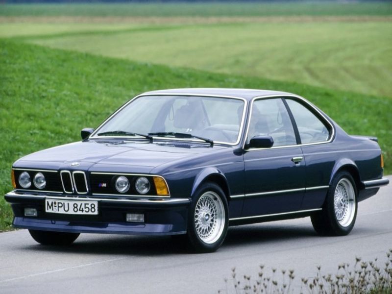
Selbstverständlich ist die legendäre erste Generation der 6er-Reihe nicht in Vergessenheit geraten. Vermutlich wird sich noch jeder an den E24 635CSi von Benno Berghammer in der Fernsehserie "Der Bulle von Tölz" erinnern können.
Jedoch ist eine Codierung der 6er-Reihe vor dem Model E63 | E64 nicht möglich.
Trotzdem möchte ich euch einige Informationen zum Vorgänger als Memorandum nicht vorenthalten:
E24 1975 - 1989
Verfasser: Markus Plamberger
Letzte Änderung: 2018-09-09 19:59
Keine Frage die Vorgänger des E38 sind fantastische Fahrzeuge und ich möchte diese auf keinen Fall stiefmütterlich behandeln.
Jedoch ist eine Codierung der 7er-Reihe vor dem Model E38 nicht möglich.
Trotzdem möchte ich euch einige Informationen zu den Vorgängern als Memorandum nicht vorenthalten:
E23 1977 - 1986

E32 1986 - 1994

Verfasser: Markus Plamberger
Letzte Änderung: 2018-08-06 03:46
Selbstverständlich ist die legendäre erste Generation der 8er-Reihe nicht in Vergessenheit geraten. Wie könnte man sich an diesen Traum von Fahrzeug nicht erinnen.
Jedoch ist eine Codierung der 8er-Reihe vor dem Model G14 | G15 nicht möglich.
Trotzdem möchte ich euch einige Informationen zum Vorgänger als Memorandum nicht vorenthalten:
E31 1989 - 1999

Verfasser: Markus Plamberger
Letzte Änderung: 2018-09-10 01:42
Die MP3 Funktionalität kann bei VFL & LCI Fahrzeugen mit Navigation Business, Navigation Professional oder Radio Professional nachgerüstet werden.
Wenn Sie ein Navigationssystem ab Werk verbaut haben, kann die Funktionalität nachgerüstet werden. Ausnahmen bestehen beim 7er E65.
Fall Sie kein Navigationssystem verbaut haben, ist zu überprüfen, ob Radio Professional vorhanden ist. Dazu muss im Menü Radio der Punkt "Alle Sender" vorhanden sein. Ist dies der Fall, kann ebenfalls die MP3 Funktionalität nachgerüstet werden.

Bei Fahrzeugen, welche noch die ersten Softwareversionen haben, muss ein Software Update duchgeführt werden.
Preis: 49,00 € inkl. MwSt.
Verfasser: Markus Plamberger
Letzte Änderung: 2018-08-06 03:39
Für gewöhnlich können die Außenspiegel nur mit der Taste im Innenraum angeklappt werden.
Die kann geändert werden, dass beim Verriegel über dei FFB und längerem halten der Taste die Spiegeln ebenfalls angeklappt werden.
Beim Entriegeln des Fahrzeugs werden diese wieder ausgeklappt.
Preis: 19,00 € inkl. MwSt
Verfasser: Markus Plamberger
Letzte Änderung: 2018-08-03 03:45
Im HUD wird kein Status bzw. keine Blinkeranzeige angezeigt.
Dies kann ergänzt werden und somit die Blinkeraktivität leicht gesehen werden.
Voraussetzung ist ein ab Werk verbautes HUD.
Preis: 19,00 € inkl. MwSt.
Verfasser: Markus Plamberger
Letzte Änderung: 2018-08-03 04:02
Der Widerstand im High-Controller beim erreichen vom Ende einer Liste wird entfernt. Als Konsequenz daraus können das Telefonbuch und MP3 Listen wesentlich schneller durchgeblättert werden und das iDrive System wird flüssiger in der Bedienung.
Voraussetzung: Navigation Professional CCC (großes Display)
Diese Funktion sollte mit dem CCC-Update 1 ab 03/2007 ab Werk gesetzt sein.
Preis: 19,00 € inkl. MwSt.
Verfasser: Markus Plamberger
Letzte Änderung: 2018-09-10 02:29
Die Alarmanlage wird sowohl über Fernbedienung als auch über Türschloss entschärft. D.h. wird das Türschloss geknackt, wird automatisch auch die Alarmanlage entschärft und das Fahrzeug kann ohne einen Mucks der Alarmanlage gestohlen werden.
Eine Änderung der Alarmanlage ist möglich, dass diese nur über die Fernbedienung entschärft werden kann. Öffnet man die Tür mithilfe des Notschlüssels über das Türschloss, wird der Alarm ausgelöst.
Voraussetzung: DWA ab Werk
Preis: 29,00 € inkl. MwSt.
Verfasser: Markus Plamberger
Letzte Änderung: 2018-08-03 04:14
Bei eingelegtem Rückwärtsgang wird das Spiegelglas des ASP auf der Beifahrerseite nach unten geneigt. Damit wird die Sicht, z. B. beim Einparken, auf die Bordsteinkante oder andere bodennahe Hindernisse verbessert."
Dabei muss der Schalter der Spiegelverstellung auf der linken Position stehen.
Voraussetzungen:
ASP mit Sonderausstattung wie Lichtpaket, automatisch Abblendend oder Anklappfunktion.
elektrische Sitzverstellung mit Memory Funktion bis 09/2005
Preis: 29,00 € inkl. MwSt.
Verfasser: Markus Plamberger
Letzte Änderung: 2020-06-28 13:00
Sollte es einmal zu einer heiklen Situation kommen, kann über die Taste auf der Funkfernbedienung durch langes betätigen die Alarmanlage ausgelöst werden.
Voraussetzung: DWA (Diebstahlwarnanlage)
Preis: 19,00 € inkl. MwSt
Verfasser: Markus Plamberger
Letzte Änderung: 2018-09-10 02:37

Das Fußraummodul (FRM) ist eine elektronischer Knotenpunkt im fahrerseitigen Fußraum.
Das Fußraummodul nimmt die Signale von den Türen auf und steuert die Beleuchtung.
Das Fußraummodul steuert auch die adaptiven Scheinwerfer.
Das Fußraummodul ist auch die Schnittstelle zum Armaturenbrett.
FRM Versionen:
Folgende Komponenten liefern Signale für das Fußraummodul:
Eine Anzahl von Steuereinheiten ist an dem Beleuchtungssystem beteiligt. Im engeren Sinne sind folgende Steuereinheiten an der Beleuchtung beteiligt (in alphabetischer Reihenfolge):
Folgende Komponenten werden gesteuert:
Verfasser: Administrator
Letzte Änderung: 2018-12-02 02:17
Die Kurzschlussbehandlung im Fußraummodul ist abhängig vom Produktionsdatum des Fußraummoduls. Unterschiede ergeben sich zum Produktionsdatum 09/2007 und 09/2009.
Beschreibung Kurzschlussbehandlung bis 09/2007:
Wenn ein Kurzschluss in einem Stromkreis erkannt wird, wird dieser Stromkreis nach 1 Minute ausgeschaltet. Dieser Stromkreis bleibt ausgeschaltet, bis ein Klemmenwechsel (Klemme 15 > Klemme 30 > Klemme 15) stattfindet. Ein erneuter Einschaltversuch wird erst nach einem Klemmenwechsel unternommen. Wenn in einem Fahrzeug insgesamt 50 Klemmenwechsel stattgefunden haben, während ein Kurzschluss in einem Stromkreis vorhanden war, wird der entsprechende Ausgang vom Fußraummodul für immer abgeschaltet . Dies ist der Fall, wenn trotz Reparatur des Kurzschlusses, der Fehlerspeichereintrag nicht mehr gelöscht werden kann. Ausnahme Xenon-Lampen: Wenn der Kurzschluss im Stromkreis einer Xenon-Lampe vorhanden war, wird der Ausgang nach 20 Klemmenwechseln für immer abgeschaltet. In diesem Fehlerfall muss laut BMW das Fußraummodul getauscht werden.
Beschreibung Kurzschlussbehandlung ab 09/2007:
Wenn ein Kurzschluss in einem Stromkreis erkannt wird, wird dieser Stromkreis nach 1 Minute ausgeschaltet. Dieser Stromkreis bleibt ausgeschaltet, bis ein Klemmenwechsel (Klemme 15 > Klemme 30 > Klemme 15) stattfindet. Ein erneuter Einschaltversuch wird erst nach einem Klemmenwechsel unternommen. Wenn in einem Fahrzeug insgesamt 10 Klemmenwechsel stattgefunden haben, während ein Kurzschluss in einem Stromkreis vorhanden war, wird der entsprechende Ausgang vom Steuergerät dauerhaft abgeschaltet. Nach Reparatur des Kurzschlusses wird über einen Diagnosebefehl im Testmodul der Ausgang wieder aktiv geschaltet. Wenn der Kurzschluss noch vorhanden ist, wird der Ausgang nach 1 Minute wieder ausgeschaltet und nach weiteren 10 Klemmenwechseln wieder dauerhaft abgeschaltet. Ausnahme Xenon-Lampen: Wenn der Kurzschluss im Stromkreis einer Xenon-Lampe noch vorhanden ist, wird der Ausgang nach 1 Minute wieder ausgeschaltet und nach 4 Klemmenwechseln wieder dauerhaft abgeschaltet.
Ein Ausgang kann 5-mal durch einen Diagnosebefehl im Testmodul wieder aktiv geschaltet werden. Wenn also insgesamt 60 Klemmenwechsel stattgefunden haben, während ein Kurzschluss im Stromkreis vorhanden war, wird der entsprechende Ausgang vom Fußraummodul für immer abgeschaltet .Ausnahme Xenon-Lampen: Ein Xenon-Ausgang kann 5-mal durch einen Diagnosebefehl im Testmodul wieder aktiv geschaltet werden. Wenn also insgesamt 24 Klemmenwechsel stattgefunden haben, während ein Kurzschluss im Stromkreis vorhanden war, wird der entsprechende Ausgang vom Fußraummodul für immer abgeschaltet. Der Ausgang kann auch mit dem Diagnosebefehl nicht wieder aktiv geschaltet werden und der Fehlerspeichereintrag kann nicht mehr gelöscht werden. In diesem Fehlerfall muss laut BMW das Fußraummodul getauscht werden.
Beschreibung Kurzschlussbehandlung ab 09/2009:
Wenn ein Kurzschluss in einem Stromkreis erkannt wird, wird dieser Stromkreis nach 10 Sekunden ausgeschaltet. Dieser Stromkreis bleibt ausgeschaltet, bis ein Klemmenwechsel (Klemme 15 > Klemme 30 > Klemme 15) stattfindet. Ein erneuter Einschaltversuch wird erst nach einem Klemmenwechsel unternommen. Wenn in einem Fahrzeug insgesamt 10 Klemmenwechsel stattgefunden haben, während ein Kurzschluss in einem Stromkreis vorhanden war, wird der entsprechende Ausgang vom Steuergerät dauerhaft abgeschaltet. Nach Reparatur des Kurzschlusses wird über einen Diagnosebefehl im Testmodul der Ausgang wieder aktiv geschaltet. Wenn der Kurzschluss noch vorhanden ist, wird der Ausgang nach 10 Sekunden wieder ausgeschaltet und nach weiteren 10 Klemmenwechseln wieder dauerhaft abgeschaltet. Ausnahme Xenon-Lampen: Wenn der Kurzschluss im Stromkreis einer Xenon-Lampe noch vorhanden ist, wird der Ausgang nach 10 Sekunden wieder ausgeschaltet und nach 4 Klemmenwechseln wieder dauerhaft abgeschaltet. Ein Ausgang kann 5-mal durch einen Diagnosebefehl im Testmodul wieder aktiv geschaltet werden. Wenn also insgesamt 60 Klemmenwechsel stattgefunden haben, während ein Kurzschluss im Stromkreis vorhanden war, wird der entsprechende Ausgang vom Fußraummodul für immer abgeschaltet .Ausnahme Xenon-Lampen: Ein Xenon-Ausgang kann 5-mal durch einen Diagnosebefehl im Testmodul wieder aktiv geschaltet werden. Wenn also insgesamt 24 Klemmenwechsel stattgefunden haben, während ein Kurzschluss im Stromkreis vorhanden war, wird der entsprechende Ausgang vom Fußraummodul für immer abgeschaltet. Der Ausgang kann auch mit dem Diagnosebefehl nicht wieder aktiv geschaltet werden und der Fehlerspeichereintrag kann nicht mehr gelöscht werden. In diesem Fehlerfall muss das Fußraummodul laut BMW getauscht werden.
Diese Abschaltung lässt sich dennoch zurücksetzen und das Fußraummodul muss NICHT getauscht werden.
Preis: 69,00 € inkl. MwSt.
Verfasser: Markus Plamberger
Letzte Änderung: 2018-12-02 02:09
Drive Away Protection System (EWS)
Model: EWS I/EWS II/EWS III/EWS III D E31/E34/E36/E38/E39/E46/E52/E53
Production Date: All since 1/94
Objectives
After completion of this module you should be able to:
Explain the differences in the EWS systems.
List the components that make up the different EWS systems.
Describe the operation of each system.
Understand and relate the data exchange sequence between the EWS and DME.

Drive Away Protection
The first version of Drive Away Protection was installed on production vehicles 9/93 through 12/93.
Purpose of The System
The purpose of the Drive Away Protection system was to reduce vehicle theft as mandat- ed by the European Insurance Commission to combat the high theft rate in European Countries.
This first version of the Drive Away Protection System added a circuit from the General Module to the DME. The added circuit was spliced into the existing code function from the Board Computer (BC) to the DME.
The components of the Drive Away Protection System are:
Door Lock Switch
General Module
Board Computer
• DME
System Components Door Lock Switch
The door lock switch provides a 12V (High) signal to the GM when the vehicle is locked from the outside. The switch also provides a Low signal to the GM when the vehicle is unlocked.
General Module
The GM receives the lock and unlock signals from the door lock switch and signals the DME with a 12V High signal when the vehicle is double locked or with a Low signal when this vehicle is unlocked.
Board Computer
The Board Computer (BC) through its’ code function provides a High signal to the DME to disallow vehicle operation or a Low signal to allow vehicle operation.
DME
The DME looks for a High/Low signal from the BC or GM and dependent on the signal, it will either allow or prevent vehicle operation.

Principle of Operation
When the vehicle is locked from the outside, a High signal is sent to the GM from the door lock switch. The GM receives this High signal and outputs a High signal to the DME. The circuit from the GM is spliced into an existing circuit from the BC to the DME.
A High signal from the GM (or BC) causes the DME to cancel the fuel and spark functions to the engine resulting in a no-start condition. The vehicle must be unlocked with the key or the code function of the BC cancelled for the DME to allow engine operation.
Lock
Double Lock Switch
Double Lock
Additional Circuit
12V

Not Active

0V
Active
Code Function
8510101
The status pages of the ZKE and DME will show the condition of the Drive Away Protection signal as High/Active or Low/Not Active.

EWS I
EWS I was installed on vehicles beginning production 1/94, replacing the original Drive
Away Protection System.
Purpose of the System
The next level of compliancy with the European Insurance Commission required additional changes from the previous system. An additional component was added called the Starter Immobilization Relay. This relay module provides added theft prevention and safety fea- tures.
At the time of introduction the system was referred to as Electronic Drive Away Protection which in German is Electronische Wegfahrsperre or EWS.
The EWS I system consisted of the following components:
Starter Immobilization Relay
Door Lock Cylinders and Switch
General Module
Board Computer (if equipped)
Transmission Range Switch
DME Engine Speed Signal (Beginning 6/94 Production)
DWA (E31)
System Components Starter Immobilization Relay
The Starter Immobilization Relay was installed on E31, E34 and E36 vehicles. It was in the following location:
E36 -In the relay carrier to the left of the steering column. E31/E34 -In the “A” pillar above the footwell kick panel speaker.
8510104
The Starter Immobilization Relay functions as a “Smart Relay”, a relay which receives inputs from various sources looking at the proper combination of input signals before activating a component, in this case the starter.
The Starter Immobilization Relay receives input from:
Ignition Switch
Trans Range Switch
And processes output to: • Starter
• General Module • DME (>6/94)
• DME
• Board Computer


EWS I - Starter Immobilizer Relay


Code
After 6/94
8510103


Range Switch
Driveaway Protection Signal

Door Lock Cylinders and Switch
The door lock cylinders and switch input a High/Low signal into the GM informing the GM of lock status. The signal is High when the system is in Double Lock.
General Module
The GM receives the High/Low signal from the door lock switch and outputs a High/Low signal to the Starter Immobilization Relay. A High signal indicates the vehicle is in Double Lock.
Board Computer
The Board Computer outputs a High/Low signal to the Starter Immobilization Relay. A High signal indicates the Code function is active.
Transmission Range Switch
The Transmission Range Switch input with automatic transmission equipped vehicles allows the Starter Immobilization Relay to provide a Neutral safety switch function. A High signal from the Trans range switch indicates the transmission is in Park or Neutral. A Low signal indicates the transmission is in a drive gear and will prevent starter operation.
DME
The DME is both an input device (after 6/94) and an output device of the Starter Immobilization Relay.
Input
Starting with production 6/94, the DME “TD” (engine speed) signal was added to the inputs of the Starter Immobilization Relay. This additional input allows the relay to provide a starter protection feature. The internal relay contact (starter operation) opens if the TD signal exceeds 60 Hz which equals the following engine speeds:


4 cylinder
6 or 12 cylinder
8 cylinder
=1800 RPM =1200 RPM =900 RPM
The relay contacts will close when the exceeded Hz value drops to 5Hz below the maxi- mum value. This is intended as a safety feature to prevent starter motor activation when the engine is running above these speeds.
Output
The DME receives a High/Low signal from the Starter Immobilization Relay. When the sig- nal is High, the DME does not activate injector or ignition operation.
DWA (E31)
The DWA outputs a High/Low signal to the Starter Immobilization Relay indicating the con- dition of the alarm system. A High signal indicates the alarm is armed, preventing vehicle starting.
Principle of Operation
The EWS Starter Immobilization Relay receives it’s inputs from the Ignition switch, GM (or DWA), BC, Trans Range Switch and the DME (after 6/94). The relay will prevent engine starting if:
The vehicle is locked from the outside. The GM receives the High signal from the door lock switch and sends a High signal to the EWS.
The BC Code function is set.
A DWA High signal is received. (E31only)
A Low signal is received from the Trans Range Switch.
The engine speed signal from the DME exceeds 60Hz. (after 6/94)
The Ignition and injection functions of the DME are disabled and the KL50 start signal to the starter is opened to prevent starter operation.
Workshop Hints:
Starter Immobilization Relays are different for manual and automatic vehicles, check to ensure correct relay is installed.
The Starter Immobilization Relay is not on the Diagnostic Link. Conventional troubleshooting techniques using the DISplus, a DVOM and the correct ETM are necessary.
Loss of input from the GM or BC will allow the engine to start.
Loss of input from the Trans Range Switch will NOT allow the engine to start.
EWS II
Starting with 1/95 production, all vehicles were equipped with a new EWS system, EWS II. This change was once again brought about to meet the next level of compliancy with the European Insurance Commission regulations.
Purpose of The System
Changes to the European Insurance Commission regulations made it necessary to intro- duce a new theft protection system with greater capabilities and a higher level of security. The EWS II system operates independent of the mechanical key. The mechanical key only makes a request of the vehicle starting system. Verification of the key electronically is required before the starting procedure is initiated.
The system features wireless communication between a programmed EEPROM housed in the ignition key and the EWS II control module. A key which is properly coded to the EWS II control module is required before starting operation continues. The EWS II and the DME control modules are synchronized through an Individual Serial Number (ISN).
The ISN, stored in the EWS II, must match that of the DME every time the ignition is switched “ON” before engine operation is allowed.
EWS II was installed on E31, E34, E36, E38 and E39 vehicles.
Major components of the EWS II system are:
Key with Transponder
Ring Antenna
Transmitter/Receiver Module
EWS II Control Module
DME Control Module
EWS II


System Components Key with Transponder
Four keys are initially supplied with each vehicle. Each key contains a wireless electronic chip (transponder chip). The function of the transpon- der is to receive and transmit data to the EWS II control module. The transponder contains a wireless read/write EEPROM in addition to a small capacitor and coil for self power capabili- ties.
The functions of the EEPROM are:
Store codes for key identification, password and changing codes.
Receive and respond to coded messages from the EWS II control module.
Power for the transponder is produced through the inductive coil and stored in the capac- itor. Each time the key is inserted into the ignition AC voltage in the antenna ring induces voltage in the inductive coil.


All keys either with remote or without, includ- ing wallet and valet keys contain transponders.

Capacitor
Key Notes:
Keys have temperature oper- ating range of -400 to 800C.
Keys are shock resistant from a height of 10 meters.
Inductive coil
8510107

Read/Write EEPROM


Ring Antenna
The Ring Antenna is an inductive coil installed around the lock cylinder which provides power for the transponder in the key and the communication link (antenna) between the key and the transmit/receive module.

Ring Antenna

8510109
Inductive coil
Transmitter/Receiver Module
The Transmitter/Receiver module supplies power to the transponder through the ring antenna and controls the flow of data between the transponder and the EWS II control module.
Data transmission between the transmitter/receiver module and the transponder takes place over a radio frequency of 125 KHz amplitude modulated AM signal.
The transmitter/receiver module converts the analog data received through the AM signal to digital data and transfers it to the EWS II control module over a single wire bi-directional data interface.
Ring Antenna fits around the Lock Cylinder
8510110
Transmitter/Receiver Module under Dash
Connector to EWS II Module
Workshop Hint:
On E34 and E36 models the transmitter/receiver mod- ule is located under the dash near the steering column.
On E 31, E38 and E39 models the transmitter/receiver module is located in the steering column cover on the right hand side of the column.

Transmitter Receiver Module


EWS II Control Module
The EWS II Control Module is linked to the BC, GM, DME, Trans Range switch and the starter for drive away protection operation. The module incorporates an integral starter relay and stores data and codes for communication with the transponder chip.
The function of the EWS II module is to provide improved drive away protection for the vehi- cle and it incorporates many features of previous systems:
Lock out of the starter when the code function of the BC is set.
Disable injection and ignition through the DME.
Prevent starter engagement with engine running.
Recognition of Park/Neutral position with automatic transmission. New features that have been added:
Disable injection, ignition and starter operation until a correct key is recognized.
EWS and DME synchronization through the use of the ISN.
Release of double lock when a correctly coded key is switched on. The EWS II control module stores the following data
for the key transponder inter-link:
Key identification code- up to 10 keys.
Key password.
Changing code- up to 10 keys.
Workshop Hint:
On E31, E36, E38 and E39 models the EWS II control module is located behind the glove box in the electrical carrier.
On E34 models the module is located on the drivers side of the vehicle behind the knee bolster.

8510106
Typical component locations E36 shown

Workshop Hints:
The DME is located in the E-Box.
Remember the EWS-DME link stays active for 10 seconds while testing keys for proper operation.


DME
The DME is redesigned to incorporate the new ISN code. As of production 1/95 all DME control modules will contain the unique ISN number and will not interchange with previous DME’s. The following new features are added to the DME:
Unique ISN assigned to DME during manufacture, it can not be changed, altered or overwritten.
The BC code input to the DME is eliminated.
The DME and EWS II control module must be synchronized. The DME sends the ISN to the EWS II module which stores the number for replay to the DME.
The ISN received from the EWS II module during start-up is compared to the internal ISN of the DME. The numbers must match before the start operation is allowed to con- tinue.
The ISN is sent to the DME continuously by the EWS II module with the key on.
The DME will ignore loss of the ISN after the engine is running.
The DME retains the ISN information from the EWS II module for 10 seconds after the ignition is switched off.
Restarting or switching the ignition on within the 10 seconds cancels the key identification process.

Principle of Operation
The starting sequence involves communication between all the components of the system. Any break-down in the communication process will result in a no start condition. The sequence of events for vehicle starting is as follows:
The key is inserted into the lock cylinder and switched “ON”. The transmitter/receiver module is powered through KL R. The transmitter/receiver module sends a 125kHz. AM signal to the ring antenna. The AM signal induces voltage in the key coil and pow- ers up the transponder.
Powered up, the key transponder sends the key identification code to the transmitter/ receiver module via the 125kHz AM signal (1). The transmitter/receiver module converts the AM signal to a digital signal and sends it to the EWS II control module (2).
The EWS II control module verifies the key identification code and checks to see if the key is enabled (3).
8510120
EWS II
Transponder Chip in Key
• Upon accepting the key as valid and enabled the EWS II control module sends a digital password (4) to the transmitter/receiver module, which converts the data to an AM signal(5) andsendsittothetransponderviatheringantenna(6).
EWS II
Transponder Chip in Key
8510121

Transmitter Receiver Module
Transmitter Receiver Module

If the transponder accepts the password as correct the transponder releases the changing code (7) to the transmitter/receiver module which converts this AM signal to digital (8) and sends it to the EWS II module (9).
If the changing code received by the EWS II module is correct, the status of the BC, transmission range switch and TD is examined. With correct input status the internal starter relay is energized and the starter motor begins to operate (10). At the same time the EWS II module sends the ISN to the DME via the single wire communication link (11).
If the ISN code stored in the EWS II module matches that of the DME, the drive away protection is cancelled and injection and ignition is enabled.
During the process of sending the ISN to the DME, the EWS II module sends a new changing code to the transponder through the transmitter/receiver and ring antenna.
EWS II
8510122
Transponder Chip in Key
EWS II
Workshop Hints:
The entire process takes place in under 750ms.
If the starter operates, the key has been recognized as OK and the key requires no further diagnosis. Check status of ISN in DISplus or MoDic.
Recognition of a valid key by the EWS II module caus- es it to send an unlock signal to the GM if the vehicle is in double lock.

8510124
Transmitter Receiver Module


The transponder stores the changing code until the next starting sequence.
11


10
Replacement Procedures Keys
Up to 6 additional keys may be ordered as replacement keys. The EWS II control module is codeable for only 10 keys (4 delivered with vehicle and 6 replacement).
EWS II Control Module
Replacement EWS II Control Modules must be ordered VIN specific. EWS II modules con- tain the VIN and coding from the factory to recognize the key codes. Modules from other vehicles will not recognize keys as being valid and not start the engine.
EWS II Control Modules store the Central Coding Key (ZCS) and the VIN. If the EWS II con- trol module is replaced the system must be ZCS coded (SIB 61 02 96 and TRI 61 01 95).
The EWS II module must be synchronized with the DME (aligned). There is no limit to the number of times the ISN may be changed in the EWS II module.
DME Control Module
The DME Control Module is not ordered VIN specific and must be programmed during replacement. The ISN from the new DME must
be transferred to the EWS II module using the
DISplus or MoDic.
Key Activation
Keys that are lost or stolen may be deactivated or made to not operate the starter functions. The SERVICE FUNCTIONS of the DISplus or MoDic for EWS II contains a “Bar/Release Code” function that activates and deactivates keys of the EWS II. Any key may be “Barred” except the key in the ignition at the time of deactivation. The lost or stolen key can be iden- tified by the identification of the remaining keys.
There is no limit to the number of times a key can be activated/deactivated.

Note: A “Barred” key will not start the engine, it will still unlock the vehicle.
EWS II Update
Beginning MY 1997 E31 and E36 vehicles with manual transmissions were updated to include a clutch pedal position switch. The clutch switch signal is provided by a hall-effect sensor providing a high sig- nal when the clutch is depressed.
EWS III (3.2)
The 1997 Model Year E38 is equipped with EWS III (3.2) drive away protection. E39 vehi-
cles produced 3/97 and later are also equipped with EWS III (3.2).
Purpose of the System
The major changes of the EWS III (3.2) system over the EWS II are a modified control mod- ule, revised wiring and the addition of the clutch switch input.
Output functions, starter control and ISN signal, remain the same for EWS III (3.2). Component changes are:
EWS III (3.2) Control Module.
Input From The K-Bus.
Clutch Switch.
Transmitter/Receiver Module Eliminated.
System Components
EWS III (3.2) Control Module
The EWS III (3.2) Control Module has a 13 pin connector. The transmitter/receiver module is no longer a separate module of the system with the electronic functions for the data transfer between the key transponder and the EWS control module being handled directly by the EWS III (3.2) control module. The vehicle wiring harness has been changed to reflect this modification and to route the wiring from the ring antenna directly to the EWS III (3.2) control module.
Input From The K-Bus
Reduction in wiring has also been accomplished with the use of the K-Bus for data com- munication between the GM, Door Module, IKE and the EWS III (3.2) control module. This data link provides the following signals to be communicated on one wire:
Engine Speed.
Lock and Unlock Requests.
Code Function.
Range Selector Position (Redundant Signal).
Engine Speed
The DME outputs the engine speed “TD” signal over the CAN Bus to the IKE. The IKE uses the TD information as needed and passes it on to the EWS III (3.2) via the K-Bus.

EWS III


Workshop Hint:
If the starter engages the following inputs are functioning normally:
• Key
Code Function
Trans Range (Clutch Switch)
Engine Speed
Don’t waste time diagnosing these inputs.
13 pin cable adapter P/N
61 3 190 for EWS III (3.2) diagnosis.
Lock and Unlock Requests
The lock and unlock information arrives at the GM over the P-Bus from the door module and is sent via the K-Bus to the EWS III (3.2) control module. This information informs the EWS control module the lock status of the vehicle (lock/double lock). The EWS III (3.2) con- trol module signals the GM over the K-Bus that an authorized key has been recognized and requests the doors be removed from the double lock position.
Code Function
The code function status arrives at the EWS control module over the K-Bus. This informa- tion allows/disallows vehicle operation based on code status. If a code has been set and entered correctly during the start-up, the vehicle will operate normally based on the other inputs. Entering the code incorrectly will prevent vehicle operation.
Range Selector Position
Range selector position is still provided directly to the EWS III (3.2) control module from the Transmission Range Selector Switch. Redundant information is provided over the K-Bus in case of loss of signal from the range switch.


Clutch Switch
A Hall-Effect Switch is added to the clutch system to inform the EWS III (3.2) control mod- ule of clutch status. Input from the switch replaces the signal from the Trans Range Selector Switch on manual transmission equipped vehicles. High signal status indicates the clutch is depressed and vehicle starting is allowed.
Principle of Operation
The starting sequence for the EWS III (3.2) is as follows:
The key is inserted into the lock cylinder and switched “ON”. The EWS III control mod- ule is powered through KL R and sends a 125kHz AM signal to the ring antenna. The AM signal induces voltage in the key coil and powers up the transponder.
Powered up, the key transponder sends the key identification code to the EWS III mod- ule. The EWS III module verifies the key identification code and checks to see if the key is enabled. If the key is correct and enabled, a password is sent to the transponder over the 125kHz AM signal through the ring antenna.
When the transponders accepts the password, it releases the changing code, which it received from the EWS III module during the last start-up operation, to the EWS III mod- ule via the ring antenna.
The EWS III module compares the changing code received from the transponder with the code stored in its memory and if they match the process is allowed to continue. The EWS III module looks at the other inputs for correct status (e.g. Code function not active, Transmission in P or N or clutch depressed, engine speed below specified RPM) and energizes the the internal relay to begin starter operation.
As the starter begins to operate, the EWS III module sends the ISN to the DME and if verified as correct by the DME, drive away protection is cancelled and injection and igni- tion is enabled. The EWS III module also sends a new changing code to the key transponder through the ring antenna.
Replacement Procedures Keys
Up to 6 additional keys may be ordered as replacement keys. The EWS III (3.2) module is codeable for only 10 keys (4 delivered with vehicle and 6 replacement). The keys are mechanically matched to the vehicle with the lock tumblers and electronically matched to the EWS III (3.2) through unalterable coding.
EWS III (3.2) Control Module
Replacement EWS III (3.2) Control Modules must be ordered VIN specific. The EWS III modules contain the VIN and coding from the factory to recognize the key codes. Use of EWS III modules from other vehicles will result in the keys not being recognized.
The EWS III (3.2) control module stores the ZCS coding and must be coded at time of installation. The module must be aligned with the DME so that it stores the correct ISN. There is no limit to the number of times the ISN may be changed in the EWS III module.
DME Control Module
DME Control Modules are “off the shelf” parts requiring programming during installation. The ISN of the DME is not changeable and must be transferred to the EWS III (3.2) mod- ule.
Key Activation
Keys that are lost or stolen may be deactivated or made to not operate the starter func- tions. The SERVICE FUNCTIONS of the DISplus or MoDic for EWS III (3.2) contains a “Bar/Release Code” function that activates and deactivates keys of the EWS III (3.2). Any key may be “Barred” except the key in the ignition at the time of deactivation. The lost or stolen key can be identified by the identification of the remaining keys.
There is no limit to the number of times a key can be activated/deactivated.

EWS III (3.3)
EWS III (3.3) is installed in the 1998 E38 from 5/97 production, in the 1998 E39 from 9/97 production, in the E46 beginning of production, in the E52 and E53 beginning of pro- duction.
Purpose of the System
The purpose of the EWS III (3.3) system is to add greater theft protection by providing a higher level of sophistication than previous systems. The new “Rolling Code” provides an additional theft deterrent through a changing of the ISN everytime the vehicle enters the start sequence.
Components changed in the EWS III (3.3) system include:
EWS III (3.3) Control Module.
DME Control Module.
Transmission Range Selection Input.
System Components EWS III (3.3) Control Module
The EWS III (3.3) Control Module uses the same 13 pin connector as EWS III (3.2) but func- tions differently. The EWS III (3.3) module has a “Rolling Code” ISN assigned to it during manufacture. The “Rolling Code” is burned into
the module and cannot be overwritten by ZCS
Coding or DME alignment procedures.
The “Rolling Code” is a one way signal from the EWS III (3.3) control module to the DME and is similar in operation to the data exchange between the EWS control module and the key transponder.
The “Rolling Code” will be different each time the start operation is begun. The “Codes” are taken from the “Rolling Code Table” which is assigned at the factory to the EWS III (3.3) control module and the DME.
Workshop Hint:
While it is possible to initialize a key to another vehicle to check for remote operation, use cau- tion. All keys for Both vehicles must be avail- able. The initializing process, causes loss of operation of keys previously initialized.
All keys must be initialized at the same time.

DME Control Module
The DME Control Module has changed in that it is not the source of the ISN but now only stores the “Rolling Code”. It compares the “Codes” to those sent to it by the EWS III (3.3) control module. The “Rolling Code Table” assigned to the DME must match the table in the EWS III (3.3) module. The “Rolling Code Table is “burned” into the DME during the pro- gramming of the DME and cannot be change once “burned”.
Transmission Range Selection Input
With the introduction of the SKE type connectors on Transmission Control Modules the direct input from the Transmission Range Selector Switch is eliminated. The input for range selection is now received from the AGS Control Module.
On manual transmission vehicles clutch status is input directly into the DME.
Principle of Operation
The starting sequence of the EWS III (3.3) is as follows:
(Same as EWS III (3.2)
The key is inserted into the lock cylinder and switched “ON”. The EWS III (3.3) control module is powered through KL R and sends a 125kHz AM signal to the ring antenna. The AM signal induces voltage in the key coil and powers up the transponder.
Powered up, the key transponder sends the key identification code to the EWS III (3.3) module. The EWS III (3.3) module verifies the key identification code and checks to see if the key is enabled. If the key is correct and enabled, a password is sent to the transponder over the 125kHz AM signal through the ring antenna.
When the transponders accepts the password, it releases the changing code which it received from the EWS III (3.3) module during the last start-up operation to the EWS III (3.3) module via the ring antenna.
The EWS III (3.3) module compares the changing code received from the transponder with the code stored in its memory and if they match the process is allowed to contin- ue. The EWS III (3.3) module looks at the other inputs for correct status (e.g. Code func- tion not active, Transmission in P or N or clutch depressed, engine speed below spec- ified RPM) and energizes the the internal relay to begin starter operation.


8510131
Workshop Hint:
If during diagnosis the key is switched on while the DME or EWS modules are “Disconnected”, the align- ment procedure will need to be carried out.
The “Alignment” procedure may be carried out an umlimited number of times.

8510135
New to EWS III (3.3)
While energizing the internal starter relay, the EWS III (3.3) module calculates a stored code from the “Rolling Code Table” and sends the calculated results to the DME.
On receipt of the “Rolling Code” from the EWS III (3.3) the DME calculates it’s own stored code and compares its results with the code it received from the EWS III (3.3).
If the “Codes” match the drive away protection is released and injection and igni- tion are enabled and the engine starts.
If the “Codes” do NOT match, the DME “rolls forward” to the next code according to the “Rolling Code Table” and makes the same calculations. The DME continues this “forward roll” up to a maximum of 200 times or until a match is found. Failure to find a match will result in the engine cranking but not starting.
When the ignition is switched off and no engine RPM is present in both the DME and the EWS III (3.3) control module each module will automatically “roll forward” to the next predetermined code based on the “Rolling Code Table”. This new code is used for the next starting sequence.

Workshop Hint:
A dead key battery does not affect vehicle start- ing.
Keys without replaceable batteries are not charged if the ignition is in the KLO (Off) posi- tion.
Workshop Hint:
While checking key operation, don’t forget to wait 10 seconds before inserting the next key.
You can not BAR the key in the ignition.
Replacement Procedures
Keys
Up to 6 additional keys may be ordered as replacement keys. The EWS II control module is codeable for only 10 keys (4 delivered with vehicle and 6 replacement).
EWS III (3.3) Control Module
Replacement EWS III (3.3) Control Modules are ordered VIN specific. The module is received with the same “Rolling Code Table” as the original module. Once ZCS coded, the DISplus software “resets” the current rolling code in the DME back to “Rolling Code” #1, providing synchronization of both modules.
DME Control Modules
Replacement DME Control Modules are “off the shelf” and must be programmed for the specific vehicle. After programming the DISplus software informs the EWS III (3.3) control module that a new DME has been installed. The next time the ignition is switched on, the EWS III (3.3) module will send the entire “Rolling Code Table” to the DME and reset it to “Rolling Code” #1.
The DME will automatically burn the “Rolling Code Table” into its memory. Once the table has been burned into the DME memory it can NOT be changed. For this reason once a DME is “Married” to the vehicle it will not work in any other vehicle.
Under certain condition “Alignment” of the DME and EWS III (3.3) modules may still be nec- essary. The alignment procedure only resets the code table to code #1 it does not change the “Rolling Code Table”.
Key Activation
Keys that are lost or stolen may be deactivated or made to not operate the starter func- tions. The SERVICE FUNCTIONS of the DISplus or MoDic for EWS III (3.3) contains a “bar/release code” function that activates and deactivates keys of the EWS III (3.3). Any key may be “Barred” except the key in the ignition at the time of deactivation. The lost or stolen key can be identified by the identification of the remaining keys.
There is no limit to the number of times a key can be activated/deactivated.
EWS III D
EWS III D is installed on E36/7 beginning of production 99 Model Year. The system
does not have a K-Bus input.
Purpose of the System
The purpose of the EWS III D system is to provide the highest level of drive away protec- tion available to vehicles without a K-Bus. The input side of the control module functions the same as an EWS II (no bus inputs) system with the exception of an integrated EWS module and transmitter/receiver module. The output side functions similar to an EWS III (3.3) system with “Rolling codes”. The EWS III D control module is on the D-Bus for diag- nostics.
Individual component inputs and system operation is the same as the mentioned previous systems.
Replacement Procedures
Keys
Up to 6 additional keys may be ordered as replacement keys. The EWS III D control mod- ule is codeable for only 10 keys (4 delivered with vehicle and 6 replacement).
EWS III D Control Module
Replacement EWS III D Control Modules are ordered VIN specific. The module is received with the same “Rolling Code Table” as the original module. Once ZCS codes, the DISplus software “resets” the current rolling code in the DME back to “Rolling Code” #1, providing synchronization of both modules.
DME Control Modules
Replacement DME Control Modules are “off the shelf” and must be programmed for the specific vehicle. After programming the DISplus software informs the EWS III D control module that a new DME has been installed. The next time the ignition is switched on, the EWS III D module will send the entire “Rolling Code Table” to the DME and reset it to “Rolling Code” #1.
The DME will automatically burn the “Rolling Code Table” into its memory. Once the table has been burned into the DME memory it can NOT be changed. For this reason once a DME is “Married” to the vehicle it will not work in any other vehicle.

Pin Assignments EWS III D


Workshop Hint:
With E46 Style diagnostics, check the following status’ in Diagnosis, Control Unit Functions, EWS:
• Starter Status:
Park/Neutral, BC Code active, Engine Speed, Double lock status, Starter Enabled
• Key Status:
Transmits, Changing code, Key I.D., Key number, Key Password, Key disabled
• DME Wire Status
• Selector lever/Clutch Status • Central Locking Status • Input Power •BC Code via K-Bus
Under certain condition “Alignment” of the DME and EWS III D modules may still be nec- essary. The alignment procedure only resets the code table to code #1 it does not change the “Rolling Code Table”.
Key Activation
Keys that are lost or stolen may be deactivated or made to not operate the starter func- tions. The SERVICE FUNCTIONS of the DISplus or MoDic for EWS III D contains a “bar/release code” function that activates and deactivates keys of the EWS III D. Any key may be “Barred” except the key in the ignition at the time of deactivation. The lost or stolen key can be identified by the identification of the remaining keys.
There is no limit to the number of times a key can be activated/deactivated.
8510130


System Introduced Model Features
Drive Away Protection
9/93 - 12/93 All
EWS I 1/94 - 1/95 All
EWS II 1/95
E-36 To End of Production
E36/7To MY 1998
E-34 To End of Production
E-38 To M.Y 1997
E-38 To 3/97 Production
EWS III 9/96 E 38 MY 97 3.2
E39 From 3/97 Production
EWS III 5/97 3.3
E38 MY 1998 From 5/97 Production
E39 From 9/97 Production
EWS III D MY 1999 Z3 Only
EWS

Injection/Ignition Disabled if car In Double lock
Starter Immobilizer Injection/Ignition Disable
Transponder Key
Starter Interlock
DME - EWS ISN Code
Transponder Key Starter Interlock
IDME-EWS ISN Code
K-Bus
Transponder Key Starter Interlock
K-Bus DME-EWS Rolling Code
Transponder Key Starter Interlock
DME-EWS Rolling Code
One Touch Starting
No
No
E38 Late MY 1997
Yes
V-12 and V-8 Only
Yes
V-12 and V-8 Only
No
85101103aa


Verfasser: Markus Plamberger
Letzte Änderung: 2019-11-03 22:40
Ab März 2012 wurde die Dachhydraulik verstärkt, was ermöglicht, das Dach auch bis zu einer Fahrtgeschwindigkeit von 40 km/h zu öffnen und zu schließen.
Sollte dies bei Ihrem Fahrzeug noch nicht Funktionieren, lässt sich diese Funktion codieren.
Preis: 49,00€ inkl. MwSt.
Verfasser: Markus Plamberger
Letzte Änderung: 2018-08-06 02:39
Verfasser: Markus Plamberger
Letzte Änderung: 2018-09-09 23:07
Wenn es Euch auch manchmal so geht wie mir, ist diese Funktion ein wirklich nützliches Feature.
Sofort wieß man, wenn der Beifahrer unter den Sitz ins leere greift um diesen mechanisch zu verstellen und einen anschließend fragend ansieht, dass nun ein Exkurs in Sachen Sitzverstellung beginnt.
Mit diesem Feature ist es nun möglich, den Beifahrersitz über die Tasten des Fahrersitzes zu verstellen. Bei Komfortsitzen ist ebenfalls die Bedienung der Memoryfunktion möglich.
Voraussetzung:
Preis: 49,00 € inkl. MwSt
Verfasser: Markus Plamberger
Letzte Änderung: 2018-09-10 02:13